Mesh generation
In this section, we present all the commands with features and functionalities that allow you to generate meshes starting from a series of simpler objects.
B_MeshLoft
Generates a loft based on meshes. The command will ask for a set of curves and then generate a loft that attempts to match the input curves.
Some options can be provided when running the command:
- AroundSamples: Number of mesh subdivisions around the curves.
- AlongSamples: Number of mesh subdivisions parallel to the curves.

B_EditAlongNormal
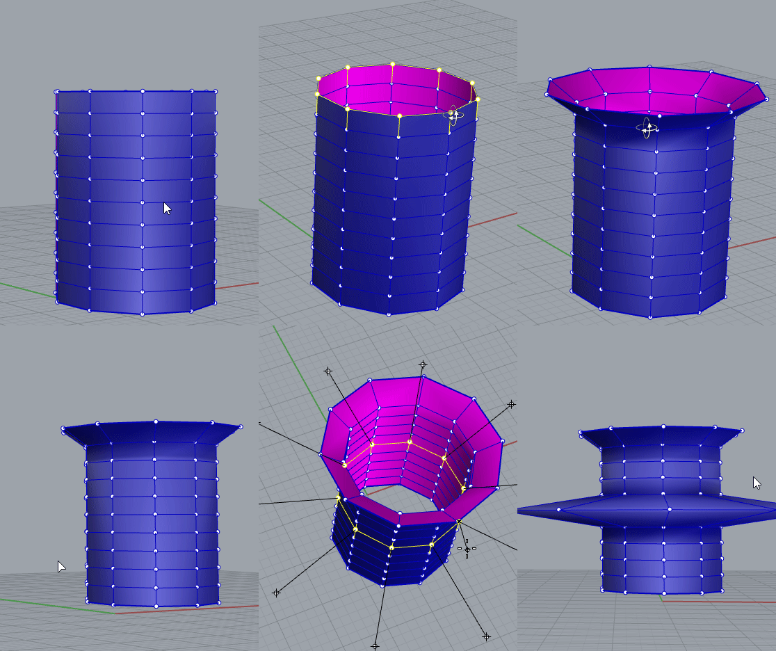
This command allows you to select an object's grips and move them along the normals, resulting in geometry modification. You can use it in two modes:
- Move: The vertices corresponding to the grips will be moved orthogonally by an amount determined by moving the pointer on the screen.
- Extrude: If you select grips on the object's naked edges, the command will create new faces with a normal orientation relative to the adjacent ones, resulting in an extrusion. Note that nothing will happen if the selected grips do not correspond to naked edges.
| Move | Extrude |
|---|---|
 |
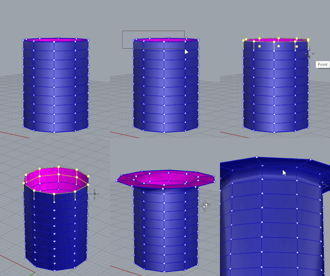 |
Object geometry edited by the B_EditAlongNormal command in Move mode and Extrude mode.
B_PlanarQuadMesh, B_PlanarTriMesh
Generates a planar quad or triangular mesh with the given edge length parameter. This command uses a special meshing process developed to optimize generation. In the first step, it is possible to select multiple curves that will be sorted so that internal curves act as holes for the generation of the quads or tris.
The second step allows you to select edge loop curves and the size of the quad to be generated. See the reference image for details.
Click here to see the tutorial.

B_DrawCrvOnMesh
This command allows you to easily draw a curve lying on a mesh by simply selecting the mesh and choosing the points you want the curve to go through. The B_EditCrvOnMesh command allows you to edit the curve after creation.

B_EditCrvOnMesh
Allows you to manipulate a curve on a mesh, which may have been created by B_DrawCrvOnMesh, or even an ordinary curve on a mesh.
B_CopyOnMesh
Generates a copy of an object on a chosen mesh, SubD, surface, or Brep. The user needs to select an object in the document and a reference plane. Then, a target object and a point on it will be requested. The reference plane is essential to establish the contact point with the object to copy. In other words, it will be used as a "carpet" to raise the object and copy it onto the tangent plane at the target point. The reference plane could be the construction plane, the WorldXY plane, or any plane provided by the user.
In the final step, it is also possible to rotate the object copy around its normal direction relative to the target mesh. At this point, the option DeleteInput will appear on the command line, allowing you to delete the original object. The entire procedure is shown below:

B_ArrayOnMesh
Generates an array of selected objects on a chosen mesh, SubD, surface, or Brep along a curve. As with B_CopyOnMesh, the user needs to select a reference plane. Then, a curve will be requested. For the command to work, the curve must lie on a mesh or equivalent. If the curve was generated using B_DrawCrvOnMesh, the target mesh will not be requested, as it is registered in the curve data.
Some options can be provided when running the command:
- Mode: Distance-based or array count (number of objects on the curve).
- Value: Distance between object copies in distance mode, or the number of copies in array count mode.
- DeleteInput: Choose whether to keep the original object or delete it.
See the result in the picture below:

B_MeshOffset
Generates an offset mesh with different offset values. Through the Botcha interface, you can easily manage points with options to Add, Remove, Select, or Move any selected point. You can choose to create a new mesh from the original or modify the existing one by toggling the Delete input option. By increasing the clustering amount, the areas of the mesh influenced by each offset point will become flatter, resulting in a clearer distinction between them.

B_MeshSnap
This command is particularly useful when building a model from a 3D scan of a shoe. It allows you to fit any last into the mesh obtained from a 3D scan. Simply overlap the rough last mesh and the scanned one and apply the modifier, selecting the scan as the Target mesh. You can also select multiple objects to snap to a target one.
The following parameters can be set:
- Maximum distance: Set the distance to search within the target mesh for a matching point.
- Target point search modes: Choose between two search modes, Raycast or Closest point, to see which delivers the best result.
- Interpolation: Select either Smooth or Linear interpolation between target points. You can also adjust the level of adherence to the target mesh for a more precise fit.


Different results depending on the level of precision.
B_Compare3D
This command allows you to compare two surface objects (mesh, brep, or subD) by the relative distance of points along their surfaces. The command uses the first object as a base reference and compares it to the second one. The second object can be quickly swapped for different ones.
The heatmap visualization highlights areas of maximum distance. This is a useful tool for comparing either two different lasts or a last with a shoe scan. The maximum distance is used as a cutoff for the distance comparison: any distance greater than the given value will be ignored.

B_Align3D
This command can be used to align two meshes to minimize their surfaces' overall distance.
It is particularly useful for preparing meshes for other commands that require aligned inputs
(e.g., B_Compare3D, B_MeshSnap, B_GradeGeometry, etc.).
The following options can be set when starting the command:
- ImprovePosition: If
True, the alignment will attempt to fit the position (e.g., overall bounding box and center) of the two meshes. - ImproveRotation: If
True, the command will attempt to minimize the rotation difference when aligning the meshes.
Note
When both options are set to True, the command can take considerable time to compute the alignment,
especially when the selected meshes are complex. A good approach is to apply the command with both improvements toggled off,
and turn them on one by one if the result is not satisfactory.
B_MeshProfileDeformer
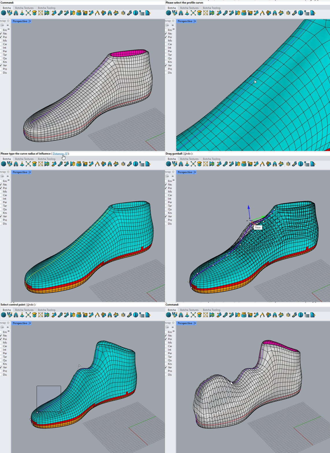
This command allows you to reshape a mesh along a selected profile while preserving its details. You will be prompted to select a curve on the mesh, which serves as the profile for manual deformation. Moving one or more of the curve's grips triggers the mesh transformation.
Additionally, you can define a fixed region: the command will ask you to select a closed curve on the mesh; vertices inside will remain stationary while others deform. You may also skip this step for greater freedom of movement. By adjusting the Distance parameter, you can define the width of the area around the profile curve where the mesh vertices will be affected.
Note
If moving the profile curve does not produce a visible deformation, the Distance parameter might be too low relative to the mesh's vertex density. Increase this value to see the desired effect.
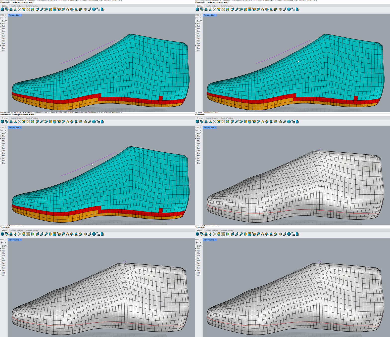
B_MeshProfileMatcher
Similar to B_MeshProfileDeformer, but the vertices along the profile curve will move to match a target curve.
B_MeshBrep
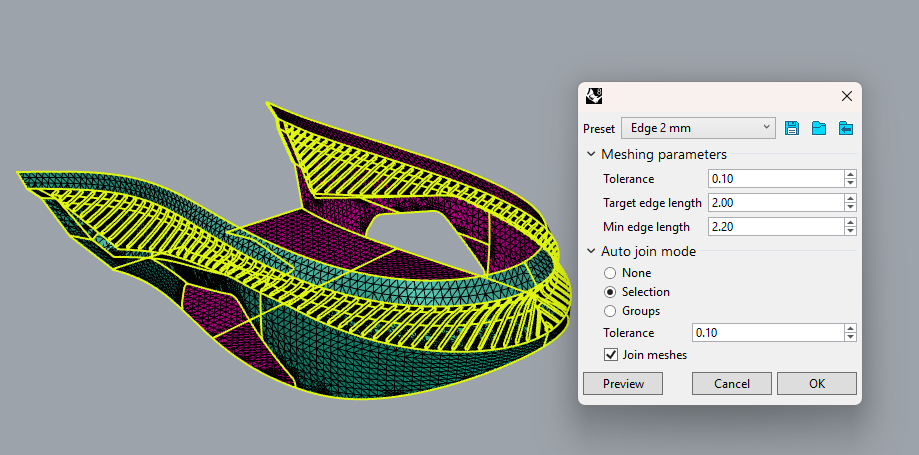
The B_MeshBrep command allows you to generate a mesh from a Brep. Upon activation, a dialog box will appear, offering the following parameters to refine your output:
- Tolerance: Defines the precision with which the new mesh approximates the input Brep.
- Target edge length: Specifies the desired average edge length for the resulting mesh.
- Min edge length: Sets the minimum allowable edge length in the final mesh.
-
Join meshes: If multiple Breps are selected, you can choose to merge the resulting meshes based on two criteria:
- By Selection: Merges all currently selected objects into a single mesh.
- By Groups: Merges objects belonging to the same Rhino group.
- Note: If the meshes do not join as expected, try increasing the Tolerance value.
To streamline your workflow across different documents or devices, you can save your current configuration as a preset, export it, or import an existing one. Before confirming, click the Preview button to verify your result.
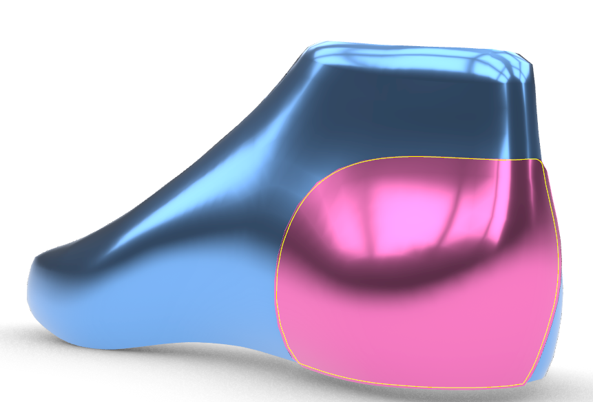
B_MakePatchOnMesh
This command generates a new mesh "patch" based on a closed curve lying on an existing mesh. You can choose between two splitting methods:
- RhinoSplit: Utilizes native Rhino splitting features to generate the geometry.
- Remapping: Reconstructs the patch based on the object's UV coordinates. If the object has clean, well-distributed UVs, Remapping typically guarantees a more regular and uniform topology, as the remeshing occurs in 2D space before being mapped back onto the 3D mesh.
Other options:
- Edge Length (EdgeLen): Defines the target length for the edges within the resulting patch.
- Complementary: The command attempts to identify the piece of mesh inside the closed curve, but if you expected the other component, simply click this option.
Before finalizing, the command asks you to select specific edge loops in the mesh preview, following a workflow similar to the B_PlanarQuadMesh command.