Utilities
These sets of commands group a number of useful features that were not relevant to any particular topic.
B_TogglePanel
Opens the panel specified by the name given as an option. The panel is opened in its current or default location; if it is in a dock bar containing more than one tab, it is set as the current tab.
Parameters
- Panel name (as text): can be UvEditor, SoftEdit, ModelOutliner, Stitching, or Colors.
B_ProjectImage
Projects an image onto a different object. The image will be taken from the bitmap (or color) texture of the selected object and assigned as a new material to the target object. Depending on the type of projection, either the camera view direction or the natural mesh direction will be used. The natural mesh direction is the average of the surface normals.
Both the source mesh and target mesh need to have valid UVs for the image to be properly calculated.
Parameters
- ProjectionDirection: Direction of the image projection.
- ImageSize: Width and height of the generated texture. If zero or negative, the original size of the image will be used. You should provide enough resolution to ensure that the generated projection is readable.
To see the tutorial, click here.
B_DeformScan
Deforms an imported image by manipulating an underlying planar mesh that uses the image as a texture material.
The workflow consists of picking a source point on the mesh and then selecting a target position to define the deformation for that specific area of the image.
Parameters
-
Morph Modes:
- Mesh: Every time a point is selected, a new vertex is created in the underlying mesh. The deformation then follows the direction of the new edges, functioning similarly to moving a skeleton where the chosen points act as joints.
- Weighted: The deformation strength at any given point is determined by its distance from the moved points. Areas closer to the moved points will experience more significant deformation.
-
Edge Length (EdgeLen): Sets the target edge dimension for the mesh used in Weighted mode. A smaller EdgeLen creates a denser mesh, resulting in a smoother and more fluid deformation.
- Transparency: Ranges from 0 to 100; controls the opacity level of the image, where 0 is fully opaque and 100 is completely transparent.
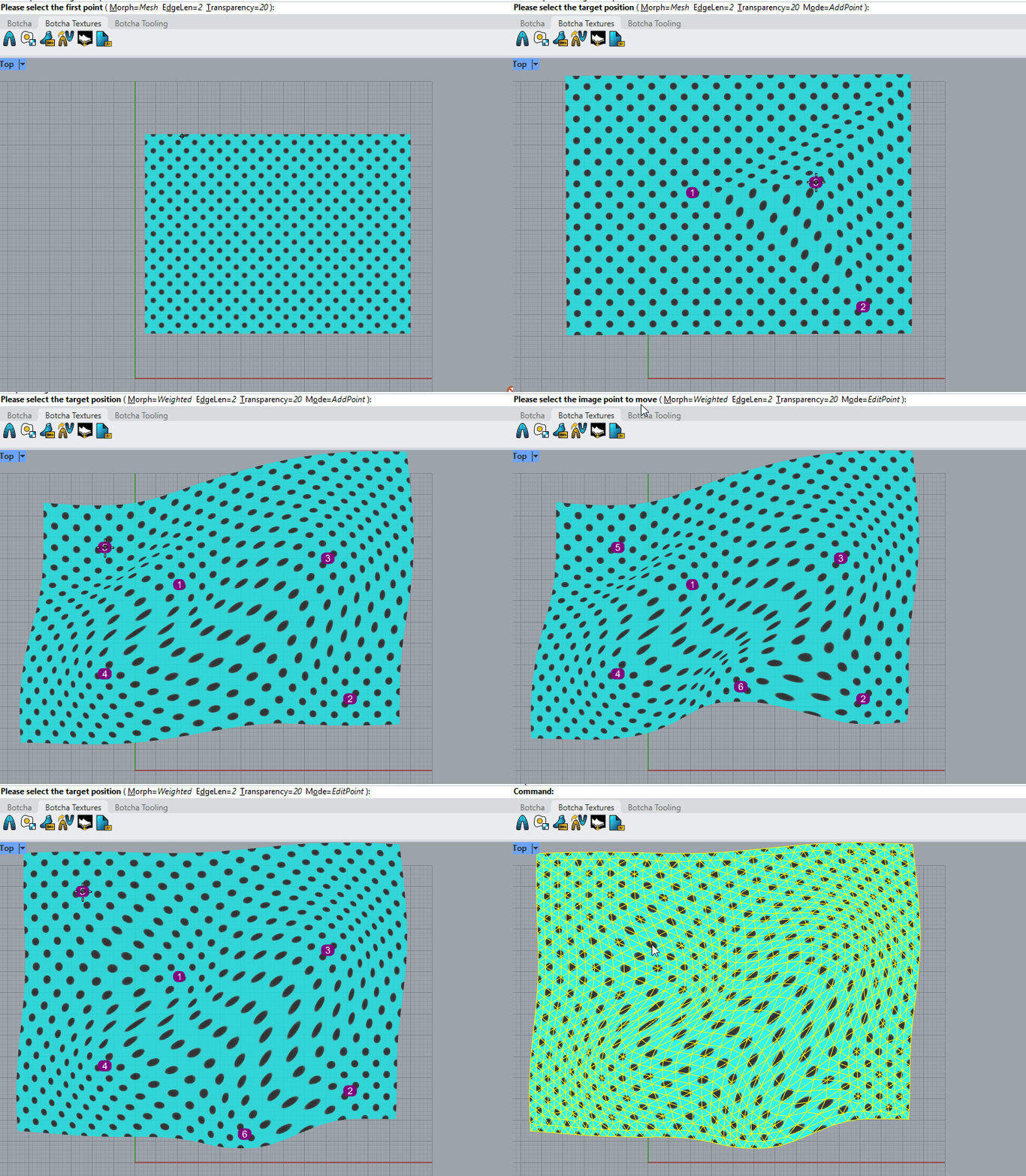
An image deformed with B_DeformScan, first using Mesh mode and then with Weighted mode. Notice that the chosen points' target positions can also be edited or removed.
B_DeformCurves
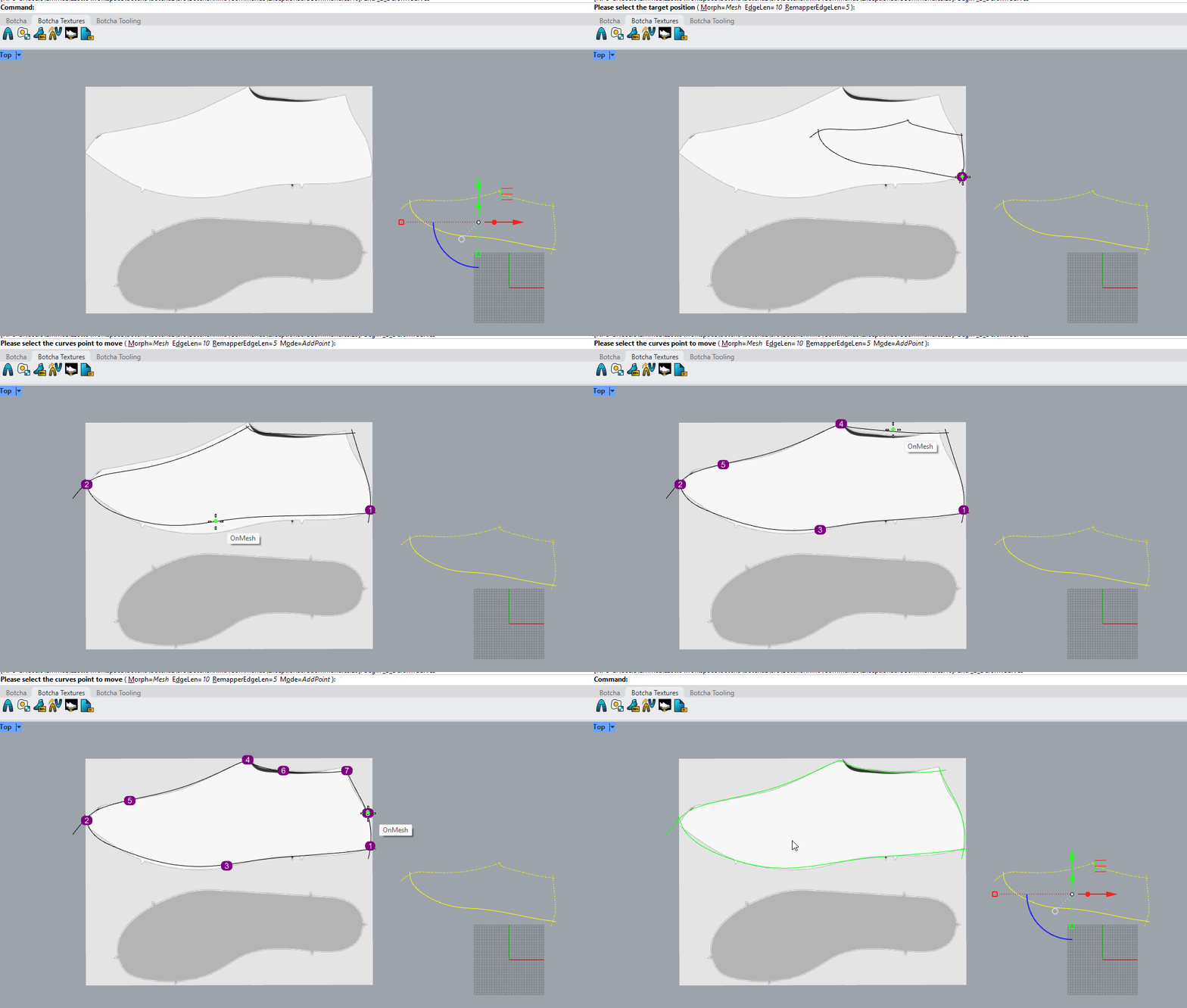
Similar to B_DeformScan, this command allows you to deform a set of curves instead of a scan. It works on the same principle, applying manipulation to an invisible mesh and continuously remapping the curves from their original positions.
Parameters
-
Morph Modes:
- Mesh: Every time a point is selected, a new vertex is created in the underlying mesh. The deformation then follows the direction of the new edges, functioning similarly to moving a skeleton where the chosen points act as joints.
- Weighted: The deformation strength at any given point is determined by its distance from the moved points. Areas closer to the moved points will experience more significant deformation.
-
Edge Length (EdgeLen): Sets the target edge dimension for the mesh used in Weighted mode. A smaller EdgeLen creates a denser mesh, resulting in a smoother and more fluid deformation.
- Remapper Edge Length (RemapperEdgeLen): The sampling distance along the curve between the points to be remapped. While a very small value increases precision, it may also reduce processing speed.
B_RemapObjects
Remaps objects from one mesh to another. The objects will need to have matching UV coordinates (textures). The remapping leverages these to match the position from one mesh to the next. You can use diverse meshes, but if the UVs match to some extent, the remapping will work.
Parameters
- Tolerance: This is the search tolerance for the remapping. It informs the tool how far to look around a given point for a match on the target mesh.
- Edge length: This is the dimension to be used for sampling. When a curve or any other object needs to be re-sampled for the mapping, this measure will be used.
- Smooth: This tells the algorithm whether to smooth the output calculation.
- Strategy: This can be either UVMap or Skinning.
- UVMap is topology-independent and allows you to use UVs to map from one object to another using texture coordinates.
- Skinning is topology-dependent; the two meshes must match, but it is faster than UV mapping.

See how to remap curves on the tutorial. Watch the videos to learn the workflow: see how to remap meshes and edit them effectively.
B_SoftEditGrips
Enables the soft edit grip and shows the panel. Soft editing allows you to change a mesh by applying a transformation proportionally to neighbors of the selected vertices. The effect of the change is visualized with colors in the mesh you are editing.

To see the tutorial, click here.
B_MergeGrips
Allows you to merge two or more grips into a single arbitrary location when editing a mesh's grips. This command can also be triggered from the related button in the Botcha Soft Edit panel. (See B_SoftEditGrips)
B_MergeMultipleGrips
Allows you to merge a set of grips, dividing them into groups based on their mutual distance. Each group is collapsed into a grip that has an average location.
Parameters
- Distance: The distance used to group grips for merging.

B_MeshProject
Projects a mesh onto another one. It is useful, for example, to make a mesh "stick" to another mesh. It is possible to choose the direction for projection in the command line; ClosestPoint allows performing the projection along the direction where the two objects are closest. In the example below, a logo has been projected onto a shoe upper part.

B_RebuildMeshNormals
Rebuilds the selected mesh's normals, considering a welding angle between face normals.
Parameters
- AngleWeld: The welding angle to consider when rebuilding normals.
B_FlowEdge
Flows a number of mesh edges to match the specified curves. You can choose multiple pairs of mesh edges and curves at the same time. The mesh is deformed to reduce distortion as much as possible.
Parameters
- Accuracy: The level of accuracy desired for similarity between the new mesh edges and the selected curves. Lower accuracy provides faster results. It ranges from 0 to 100.
- Delete input: Choose whether to keep the old mesh.

To see the tutorial, click here.
B_UnweldByCurve
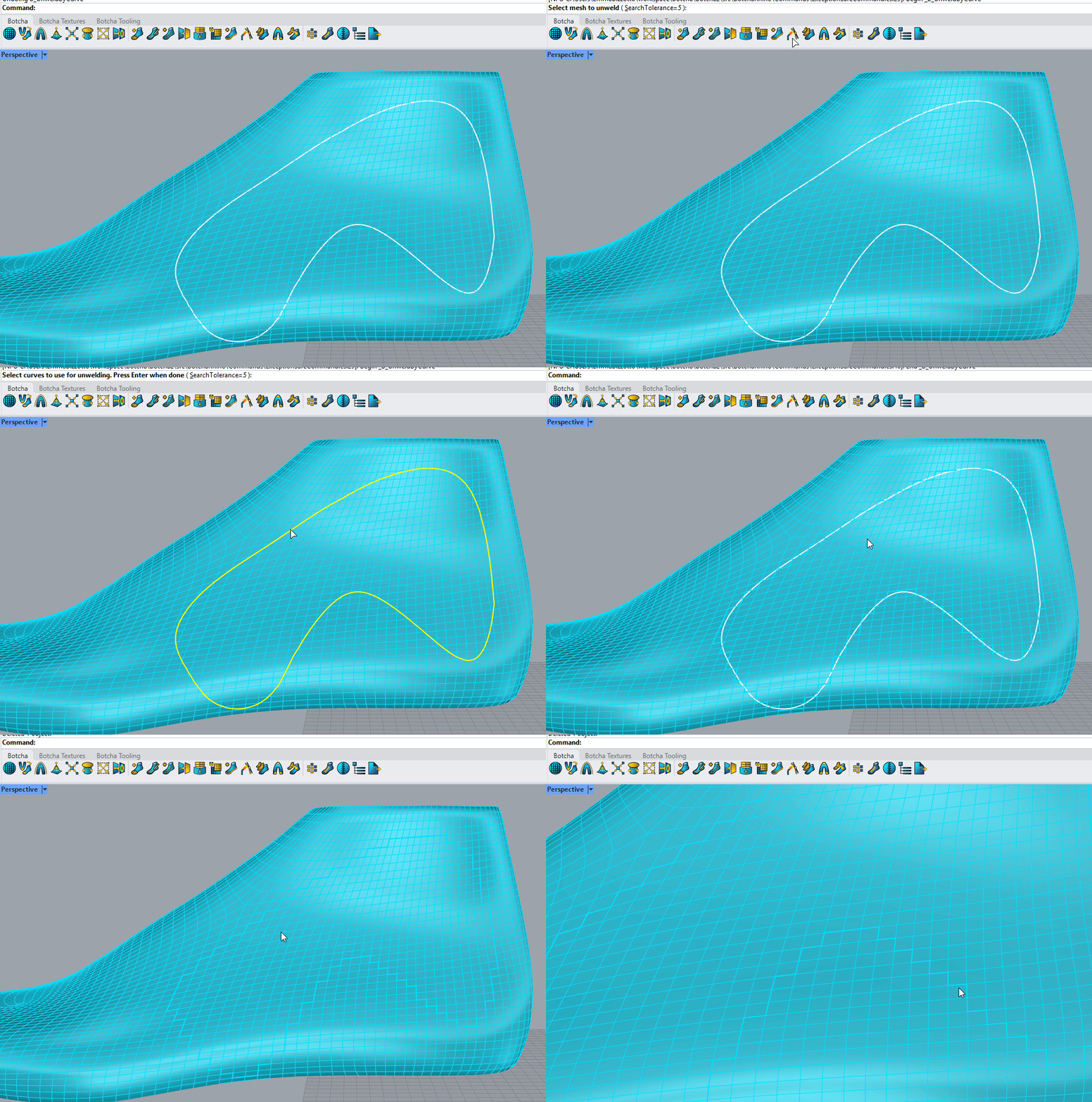
With this command, you can unweld a mesh along one or several curves. Simply select a mesh and a curve lying on it—such as one drawn with the B_DrawCrvOnMesh command. The tool will then unweld the edges along that curve based on your Search Tolerance.
B_StitchCreate
Given a mesh or surface and one or more curves lying on it, this command allows you to create stitching along the curves.
Parameters
- Pattern: The preferred stitching pattern. You can either choose a pattern from a set of given ones (Linear, DashDot, ZigZag) or create your pattern with the B_StitchPatternCreate command (see below).
- Style: The dash can take two different shapes: Rounded, consisting of a cylinder with hemispherical ends, and Curved, where the dash ends bend to the surface for a more realistic effect.
- Diameter: Diameter of any dash composing the stitching.
- ProjectOnMesh: Allows you to choose between keeping the stitching on its leading curve or projecting it onto the mesh.
Note
You can easily handle stitching generation using the Botcha stitching panel. Double-clicking on a preferred pattern represented in the panel allows you to choose the mesh and the curves where you want to create stitching.
 A linear stitching of curved style and cross rounded one
To see the tutorial, click here.
B_StitchPatternCreate
Allows you to create a custom pattern for stitching. The command will ask you to choose the curves you want your pattern to be made of and a leading line, necessary to establish the orientation of the pattern shapes and their position relative to the stitching curve they lie on.
Parameters
- DashLen: The length of any dash in the pattern. It will not be exactly as chosen but will be approximated to better fit the pattern.
- PatternName: The name of the pattern that will appear in the panel after creation.

The length of the pattern, visible in the Botcha stitching panel's Length column, corresponds to the length of the leading line.

B_BindingsCreate
Generates connecting meshes between two adjacent meshes, resembling two flaps of fabric. Stitching is automatically applied along the binding if requested.
Parameters
- Pattern: The desired binding pattern. You can find various patterns in the Botcha bindings panel. The curves represent the cross-section of the bindings perpendicular to the mesh edges upon which they are constructed. The red point indicates where the curve supporting stitchings passes.
- Depth: Depth of the binding perpendicular to the edges.
- JoinToMesh: When set to false, produces the bindings as new meshes. When set to true, incorporates them into the existing ones.
- Stitching: Generates a stitching line with dashed meshes on it.
Note
You can effortlessly manage binding generation through the Botcha bindings panel. Double-clicking on the desired pattern is equivalent to launching the command with that pattern as input.

 Binding created using the StitchAndTurn pattern.
B_LacesConstraints
This command, used together with B_LacesCreate, allows you to draw custom laces on the shoe model easily and quickly. First, place a set of constraints on the model. These are essential for determining the points the lace will pass through. Three kinds of constraints are available: eyelets, tunnels, and curved tunnels.
Call the B_LacesConstraints command and select a mesh or surface to place the constraints on. A set of options on the command line will request several parameters:
- Type: Choose which kind of constraint you are drawing. If you choose a tunnel or curved tunnel, a simple interaction will lead you to set the length of the straight and curved parts.
- Radius: Indicates the radius of the eyelets or tunnels.
- Offset: The distance to keep from the mesh for tunnels and curved tunnels. For eyelets, this value is not applicable and will be ignored.
 Straight and curved tunnel constraints
Interaction to create a curved tunnel:

Note
Constraint surfaces and curves will no longer work if they are moved, copied, or edited. Their geometry was created for that specific purpose; if modified, they lose their function. The red and blue arrows will no longer light up when calling the lace creation command.
B_LacesCreate
After using B_LacesConstraints to place constraints on the object, call this command to create the laces. You can choose all parameters for a custom lace shape in the dialog that opens.
Parameters
- Section: Choose the kind of section preferred. Flat, round, squared, and stitched sections are available.
- Width: The width of the lace. For round laces, this corresponds to the diameter.
- Thickness: The thickness (height) of the sections. This is not adjustable for round and squared laces since it equals the width.
- Piece in tunnels: Set to true if you want lace pieces created inside the tunnels.
- Extremities: Choose whether lace extremities should go inside or outside the shoe or not be drawn.
Now you can trace your lace path between constraints step by step, choosing which side of each constraint to enter. Two arrows highlight the two possible directions for crossing constraints.
 Procedure for creating a lace.

 Different kinds of lace section: round, flat, squared, and stitched.
B_LacesRemoveObjects
Use this command to remove the functionality from all constraints. They become normal surfaces and curves if you call this command. This also means that calling B_LacesCreate afterward will result in a message stating there are no constraints in the document.
B_ExportModel
Exports selected objects as glTF, GLB, or OBJ files. The command will first ask whether you want to export only selected objects or all objects in the document. If any exported objects have modifiers, they will be exported with all modifiers applied to their geometry.

B_BakeTexture
This command generates a texture that represents, pixel by pixel, the distance from the first selected object to a set of other objects. This texture can be applied as a displacement to the first object to provide details from the other geometries. Object geometries can be meshes, surfaces, or SubDs. The command has several options:
- TextureSize: The output texture resolution in pixels.
- Action: Allows you to directly add the Displace modifier to the first object's modifier stack. Choose Apply to do so.
- MaxDistance: The maximum distance accepted between a point on the first geometry and the target point on other geometries. A larger value increases the likelihood that points will experience significant displacement.
The resulting texture is saved as a .png file at a location specified by the user. A Rhino Texture is also created and can be found in the Textures panel.
Note
The object you want to displace must have texture coordinates. For meaningful displacement, ensure there are no overlapping areas in the 2D UV layout.
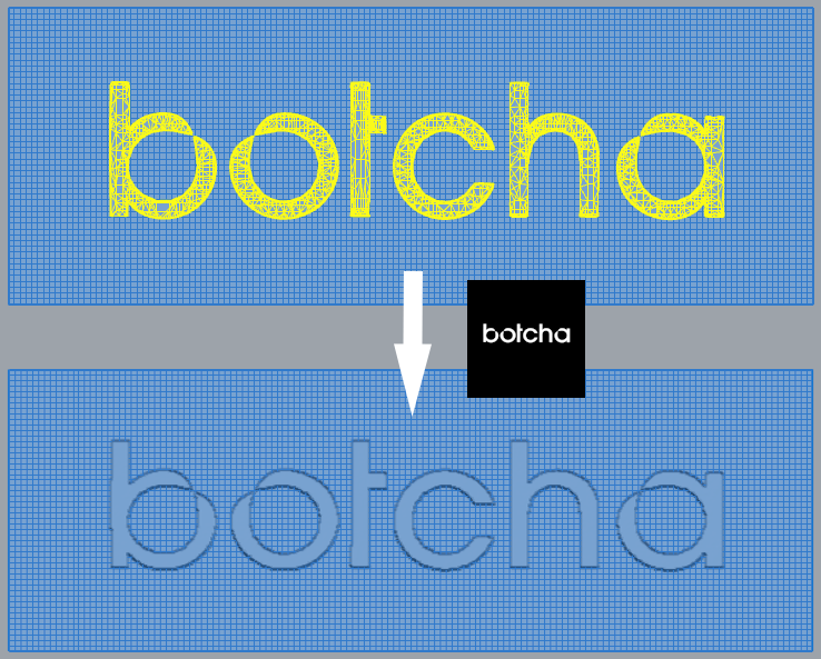
Here, the flat rectangular mesh has been embossed with the Botcha logo using a texture generated by the command (shown next to the arrow). The white pixels correspond to points that will be raised.
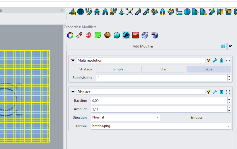 The rectangular mesh's modifiers panel shows a Displace modifier with the correct baseline and amount values, automatically generated by the command. A Multiresolution modifier has been added to better show displacement details. The texture applied is botcha.png.