Tooling Analysis
To ensure that a product can be manufactured efficiently, especially when dealing with complex injection molds or bottom units, detailed information about the geometry is essential. Tooling analysis provides the necessary insights to identify potential manufacturing issues, such as undercuts or insufficient draft angles, which could prevent the part from being removed from the mold.
Botcha offers a suite of tools designed to visually identify these critical engineering parameters quickly.
Draft Angle Analysis
Draft angle analysis is a visual tool used to evaluate the steepness of surface slopes relative to a specific Pull Direction. In mold design, surfaces must have a slight taper (the draft angle) to facilitate the release of the part from the mold cavity.
Understanding Pull Direction
The Pull Direction is the axis along which the mold halves separate. Using the B_NormalAnalysis command, you can set this vector
(typically the Z-axis for footwear bottom units) to analyze how every point on your surface relates to the release path.
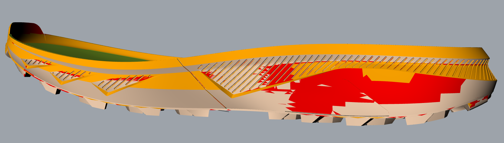
Interpreting the Visual Feedback
The analysis generates a color-coded gradient on your mesh or surface, this color coding depends on your personal settings, it does give you a colored output that is easily readable to understand which pieces of your design have angles that cannot easily allow product extraction.
Digital Textures
Before committing to a final export or sending a file to a 3D printer, it is crucial to validate the final state of the geometry, especially after applying high-resolution Digital Textures or Displacement Modifiers.
Model Outliner 
When working on complex tooling assemblies with multiple components (e.g., inserts, pins, and different mold plates), keeping track of the hierarchy and object relationships can be difficult.
The Model Outliner provides a dedicated tree view of your project, allowing you to:
- Quickly isolate specific components of the tooling.
- Identify parent-child relationships between base geometries and their derived modifiers.
- Manage visibility and lock states for large assemblies without cluttering the standard Rhino layer panel.